The optical fiber drawing tower
FIND OUT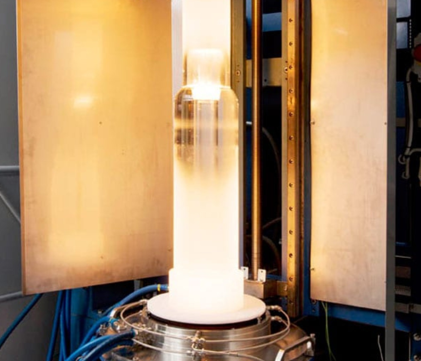
In order to meet the huge demand for optical fiber for telecommunications applications, many companies have had to build new plants and install new fiber facilities all around the world. Today, the optical fiber manufacturing process is quite similar across all the manufacturers.
However, obtaining optical fiber with the very best properties and performance levels, and with a long working life, requires a certain know-how that has remained a secret. Subsequently, the performance levels of measurement instrument, along with process control, are critical to insuring that producers’ quality standards are met.
What makes up a fiber optic drawing tower ?
The optical fiber is obtained from a multi-layer, pure glass cylinder, called the preform. This large tube (generally 20 cm around and 2 m high) is set vertically at the top of a metal tower. Because the final glass fiber is obtained by “drawing” down a droplet, it is commonly called the draw tower.
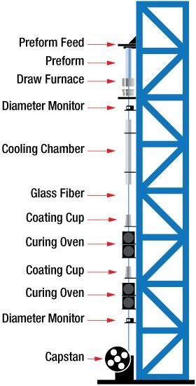
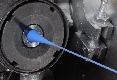
Draw towers with heights of between 30 and 45 meters are often found in the industry. Various types of equipment located from the top to the bottom of the tower are required to manufacture and control the drawing process. At the top, the furnace heats the base end of the preform to melt the glass until a droplet slowly descends, pulling out the initial glass fiber. When the glass drawing starts, a helium-filled cooling tube helps to reduce the temperature before a coating is applied. The coating application can be done in one or two steps and requires a curing oven to ensure the coating is cured before the fiber comes into contact with the pulleys. More and more frequently now, coating layers are cured with high-intensity UV LEDs (rather than incandescent lamps), to reduce electric power consumption and reduce space requirements on the tower.
Controlling the drawing process
All along the draw tower, various measurement instruments provide all of the relevant parameters needed to optimize the process:
- Diameter measurements of the bare fiber (top) and of the coated fiber (bottom).
- Position of the fiber (X-Y) and, more globally, alignment of the devices all along the draw tower.
- Drawing tension measurement to adjust the speed and temperature of the drawing process.
- Internal defect detection inside the glass, but also inside the coating layers, to prevent the optical fiber from having inadequate performance levels.
- Lump & Neckdown detection after the second coating layer.
Digital inputs and outputs, analog outputs (voltage or current), RS232, and a field bus are used to connect these devices to the tower PLC for loop requirements and measurement analysis. Globally, these specific instruments provide control capability to maintain, record and analyze product and tower parameters. Because production is 24/7 almost all year round, these devices need to be very reliable. Since increased drawing speed is an essential factor in improving the productivity of production plants, high-speed and high-accuracy performance of the devices are essential to insure complete in-line certification of the fiber.
Our articles related
.jpg)
Contact the company CERSA MCI
Do you have a specific control and measurement need?
Are you looking for a high-performance control device?
You wish to request one of our services?